Gasification Research Laboratory
Technologies
Coal and Biomass
Gasification:
Gasification is a century old technology, which flourished quite well before and during the Second World War. The technology disappeared soon after the Second World War, when liquid fuel became easily available. The interest in the gasification technology has undergone many ups and downs in running century. Today, because of increased fuel prices and environmental concern, there is renewed interest in this century old technology. Gasification has become more modern and quite sophisticated technology.
Gasification is basically a thermochemical process which converts biomass materials into gaseous component. The result of gasification is the producer gas, containing carbon monoxide, hydrogen, methane and some other inert gases. Mixed with air, the producer gas can be used in gasoline or diesel engine with little modifications.
Fig: Gasification for Energy Supply
Based on the design of gasifiers and type of fuels used, there exists different kinds of gasifiers. Portable gasifiers are mostly used for running vehicles. Stationary gasifiers combined with engines are widely used in rural areas of developing countries for many purposes including generation of electricity and running irrigation pumps. Technologies such biomass gasification which allows utilization of biomass fuel is of great importance.
Theoretically, almost all kinds of biomass with moisture content of 5-30% can be gasified; however, not every biomass fuel can lead to the successful gasification. Most of the development work is carried out with common fuels such as coal, charcoal and wood. It was recognized that fuel properties such as surface, size, shape as well as moisture content, volatile matter and carbon consent influence gasification.
The key to a successful design of gasifier is to understand the properties and thermal behavior of the fuel as fed to the gasifier. Operation of gasification system demands knowledgeable and skilled operator. Those interested in this technology must remember that it requires hard work and tolerance. Compared to conventional system such as liquid fuel run engines, biomass gasification technology is inconvenient. But it is economical at many places and may lead to self-reliance in the crucial time of fuel crisis.
Gasification Processes/Gasifiers
Design of gasifier depends upon type of fuel used and whether gasifier is portable or stationary. Gas producers are classified according to how the air blast is introduced in the fuel column. History of gasification reveals several designs of gasifiers. The most commonly built gasifiers are classified as:
- Updraft gas producer
- Downdraft gas producer
- Twin-fire gas producer
- Crossdraft gas producer
- Plasma Gasification
- Transport Gasifier
- Circulating Fluidized Bed gas producer
Updraft gas producer
An updraft gasifier has clearly defined zones for partial combustion, reduction, and pyrolysis. Air is introduced at the bottom and act as countercurrent to fuel flow. The gas is drawn at higher location. The updraft gasifier achieves the highest efficiency as the hot gas passes through fuel bed and leaves the gasifier at low temperature. The sensible heat given by gas is used to preheat and dry fuel. Disadvantages of updraft gas producer are excessive amount of tar in raw gas and poor loading capability. Hence it is not suitable for running vehicle.
Downdraft gas producer
In the updraft gasifier, gas leaves the gasifier with high tar vapor which may seriously interfere the operation of internal combustion engine. This problem is minimized in downdraft gasifier. In this type, air is introduced into downward flowing packed bed or solid fuels and gas is drawn off at the bottom. A lower overall efficiency and difficulties in handling higher moisture and ash content are common problems in small downdraft gas producers. The time (20-30 minutes) needed to ignite and bring plant to working temperature with good gas quality is shorter than updraft gas producer. This gasifier is preferred to updraft gasifier for internal combustion engines.
Twin-fire gas producer
The advantage of co-current and counter-current gasifiers are combined in a so a called twin-fire gasifier. It consists of two defined reaction zones. Drying, low-temperature carbonisation, and cracking of gases occur in the upper zone, while permanent gasification of charcoal takes in lower zone. The gas temperature lies between 460 to 520C. Total process takes place with under pressure of -30 mbar. Twin-fire gasifier produces fairly clean gas.
Cross draft gas producer
Cross draft gas producers, although they have certain advantages over updraft and downdraft gasifiers, they are not of ideal type. The disadvantages such as high exit gas temperature, poor COreduction and high gas velocity are the consequence of the design. Unlike downdraft and updraft gasifiers, the ash bin, fire and reduction zone in cross draft gasifiers are separated. These design characteristics limit the type of fuel for operation to low ash fuels such as wood, charcoal and coke. The load following ability of cross draft gasifier is quite good due to concentrated partial zones which operates at temperatures up to 2000 c. Start up time (5-10 minutes) is much faster than that of downdraft and updraft units. The relatively higher temperature in cross draft gas producer has an obvious effect on gas composition such as high carbon monoxide, and low hydrogen and methane content when dry fuel such as charcoal is used. Crossdraft gasifier operates well on dry air blast and dry fuel.
Circulating Fluidized Bed Gasifier
Circulating beds, where the fluidization suspends the particle bed, due to a larger kinetic energy of the fluid. As such the surface of the bed is less smooth and larger particles can be entrained from the bed than for stationary beds. These particles can be classified by a cyclone separator and separated from or returned to the bed, based upon particle cut size.
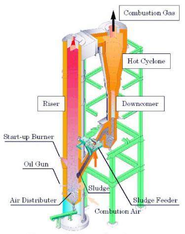
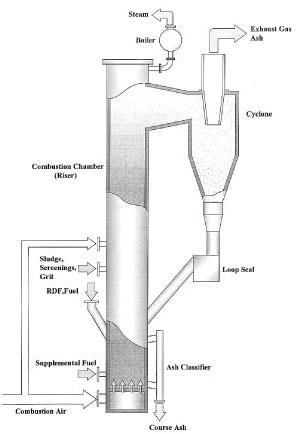
The circulating fluidized bed furnace consists of a combustion chamber (riser), a cyclone, a loop seal and an ash classifier. Silica sand, the fluidizing medium, is blown upward by the combustion air from the bottom of the riser to the top. The gas velocity inside the riser is as high as 4-6m/sec and the air is in a turbulent state. In the riser, sludge and screen residue are dried and burned rapidly, turning into fine ash except the incombustibles. The combustion ash is sent to the cyclone together with the silica sand. The sand and the ash are separated by the difference in specific gravity and particle size, and the ash is sent to the flue-gas-treating unit downstream with the exhaust gas. The sand falls into the loop seal, and is returned to the furnace. Filtration residue and the incombustibles in the sand remain and accumulate in the furnace, and must be drawn out from the ash classifier.
Plasma Gasification
Plasma gasification is the gasification of matter in an oxygen-starved environment to decompose waste material into its basic molecular structure. Plasma gasification does not combust the waste as incinerators do. It converts the organic waste into a fuel gas that still contains all the chemical and heat energy from the waste. It converts the inorganic waste into an inert vitrified glass.
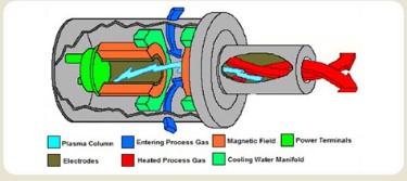
Plasma is considered a 4th state. Electricity is fed to a torch, which has two electrodes, creating an arc. Inert gas is passed through the arc, heating the process gas to internal temperatures as high as 25,000 degrees Fahrenheit. The following diagram illustrates how the plasma torch operates.
The temperature a few feet from the torch can be as high as 5,000-8000º F. Because of these high temperatures the waste is completely destroyed and broken down into its basic elemental components. There are no tars or furans. At these high temperatures all metals become molten and flow out the bottom of the reactor. Inorganics such as silica, soil, concrete, glass, gravel, etc. are vitrified into glass and flow out the bottom of the reactor. There is no ash remaining to go back to a landfill.
The plasma reactor does not discriminate between types of waste. It can process any type of waste. The only variable is the amount of energy that it takes to destroy the waste. Consequently, no sorting of waste is necessary and any type of waste, other than nuclear waste, can be processed.
The reactors are large and operate at a slightly negative pressure, meaning that the feed system is simplified because the gas does not want to escape. The gas has to be pulled from the reactor by the suction of the compressor. Each reactor can process 20 tons per hour (tph) compare to 3 tph for typical gasifiers. Because of the size and the negative pressure, the feed system can handle bundles of material up to 1 meter in size. This means that whole drums or bags of waste can be fed directly into the reactor making the system ideal for large scale production.
The gas composition coming out of a plasma gasifier is lower in trace contaminants than with any kind of incinerator or other gasifier. Because the process starts with lower emissions out of the reactor it is able to achieve significantly lower stack emissions. The gasifier doesn't care about the amount of moisture in the waste. The moisture consumes energy to vaporize and can impact the capacity and economics; however, it will not affect the process.
Transport Gasifier
The Transport gasifier is an advanced pressurized circulating fluidized bed gasifier that operates at moderate temperatures (1,500 1,950oF). The mechanical design and operation of the gasifier are based on KBRs fluidized catalytic cracking (FCC) technology, which has more than 60 years of commercial operating experience. As shown in Figure, the gasifier is simple in design and has no internals, expansion joints, valves or other moving parts. It is designed to operate using air, pure oxygen or enriched air/oxygen mixtures as oxidant. While the air-blown mode is ideally suited for power generation applications, the oxygen-blown mode and enriched air-blown mode provide syngas for chemicals and fuels synthesis.
The gasifier features a dry feed injection system and is a non-slagging gasifier. In particular, the gasifiers continuous dry ash handling system eliminates the technical difficulties associated with slag handling and removal faced by comparable slagging gasifiers. Slagging gasifiers generally require frequent refractory change out due to the erosive nature of the high temperature fluidic slag. This can escalate maintenance costs while reducing gasifier availability. In contrast, lower operating temperatures in the gasifier allow installation of conventional, cost-effective alumina-silica type refractory that has a significantly longer life.